Product Description
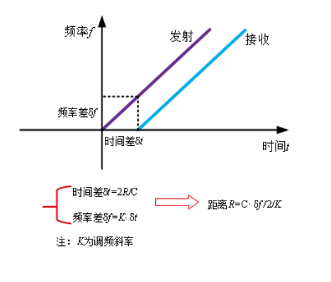
The general principle of the FM continuous wave radar level gauge is that the radar emits electromagnetic waves on the top of the tank, and the electromagnetic waves are received by the radar after being reflected by the medium. The frequency difference 6f between the received signal and the transmitted signal is proportional to the distance R from the surface of the medium: R=C(speed)*6f(frequency difference)/2/K (FM slope).Because the speed of light C and the frequency modulation slope K are known, the frequency difference 6f is estimated, and the distance R of the material surface at the radar installation position can be obtained, and then the space distance from the radar to the material surface is subtracted from the known total height of the tank body (referred to as Empty height) to get the height of the material level.
principle
The general principle of the FM continuous wave radar level gauge is that the radar emits electromagnetic waves on the top of the tank, and the electromagnetic waves are received by the radar after being reflected by the medium. The frequency difference 6f between the received signal and the transmitted signal is proportional to the distance R from the surface of the medium: R=C(speed)*6f(frequency difference)/2/K (FM slope).Because the speed of light C and the frequency modulation slope K are known, the frequency difference 6f is estimated, and the distance R of the material surface at the radar installation position can be obtained, and then the space distance from the radar to the material surface is subtracted from the known total height of the tank body (referred to as Empty height) to get the height of the material level.
80G FM Radar Level Gauge
1. Millimeter wave radar, the measurement accuracy can reach up to 2mm, and the minimum measurement blind zone is 0.1m.
2. The smaller antenna size meets the needs of more working conditions.
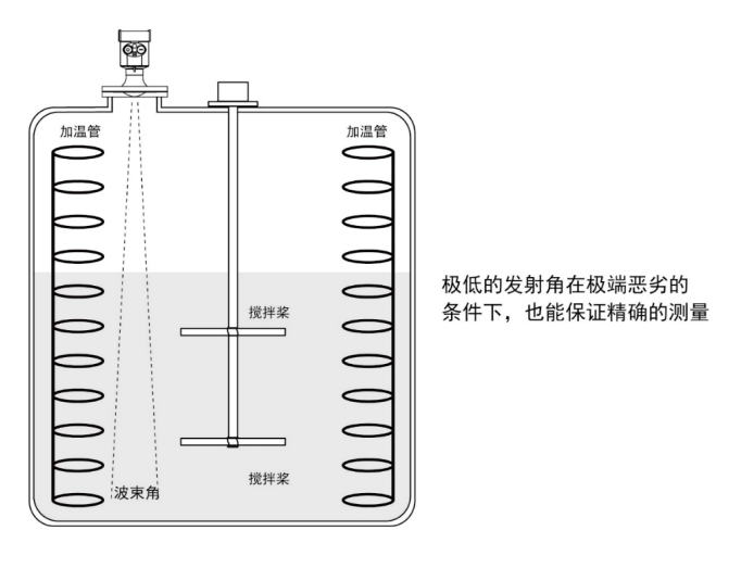
3. A variety of lens antennas, smaller emission angles, more concentrated energy, and stronger echo signals. Under the same industrial and mining conditions, it has higher reliability than other radar products.
4. With stronger penetrability, it can be used normally even in the case of adhesion and condensation.
5. The dynamic signal range is larger, and it is easier to measure low dielectric constant media.
6. Multiple measurement modes, the radar response time in fast measurement mode is less than 1S.
Installation method 1
Threaded installation (for 11S, 11, 13)
Installed at 1/4 or 1/6 of the tank diameter
The minimum distance from the tank wall shall be 200mm.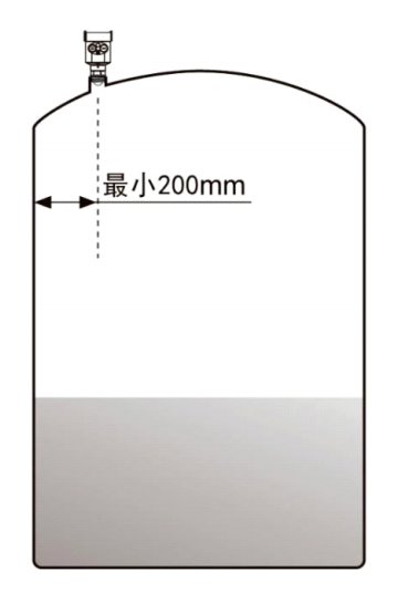
Installation method 2
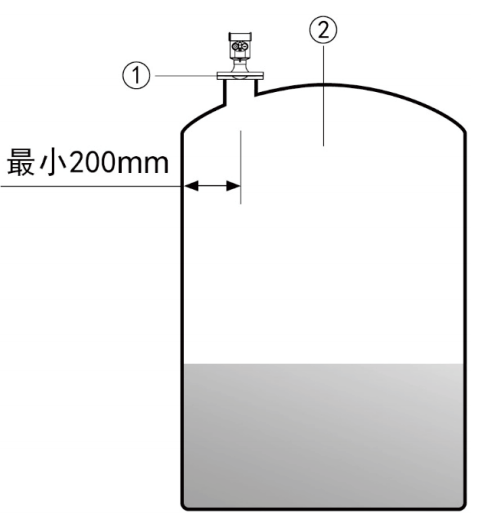
Flange installation
When using flange installation, the instrument should be installed at 1/4 or 1/6 of the tank diameter. The minimum distance between the instrument and the tank wall should be greater than 200mm.
(1) Datum plane
(2) The center or axis of symmetry of the container
Installation method 3
Hoisting (choose according to specific installation conditions)
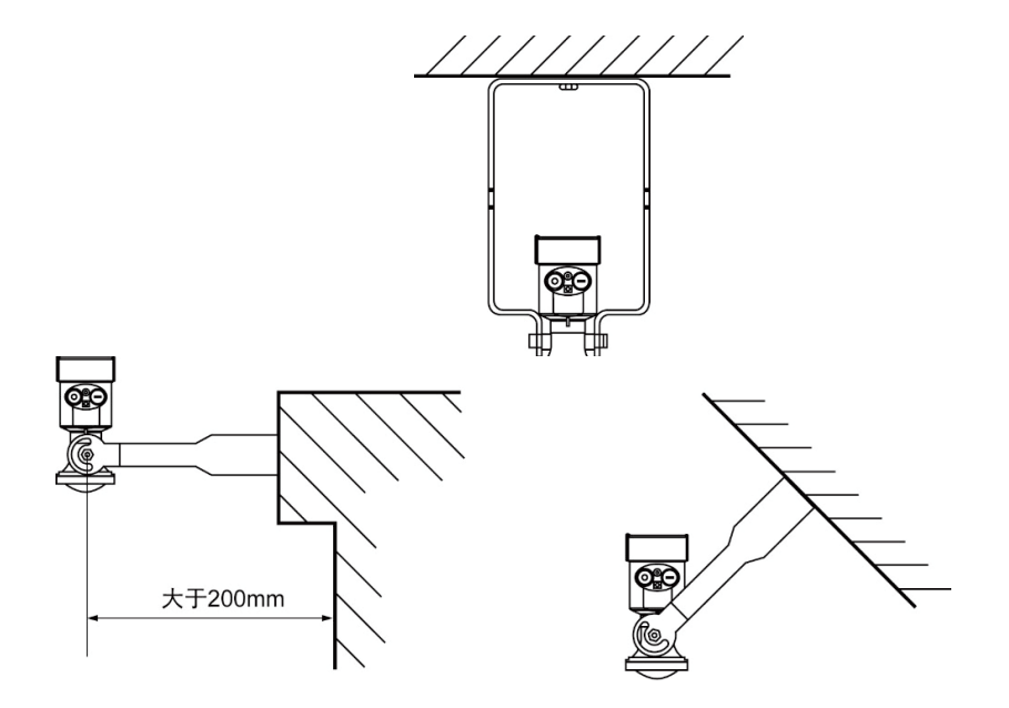
installation requirements
When using flange installation, the instrument should be installed at 1/4 or 1/6 of the tank diameter. The minimum distance between the instrument and the tank wall should be greater than 200mm.
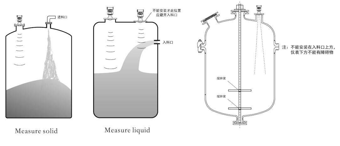
Under extremely complex working conditions, the instrument can work normally if there is no obstacle in the area with a radius of 20cm centered on the radar installation point.
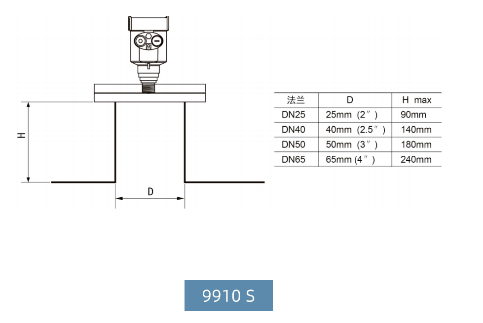
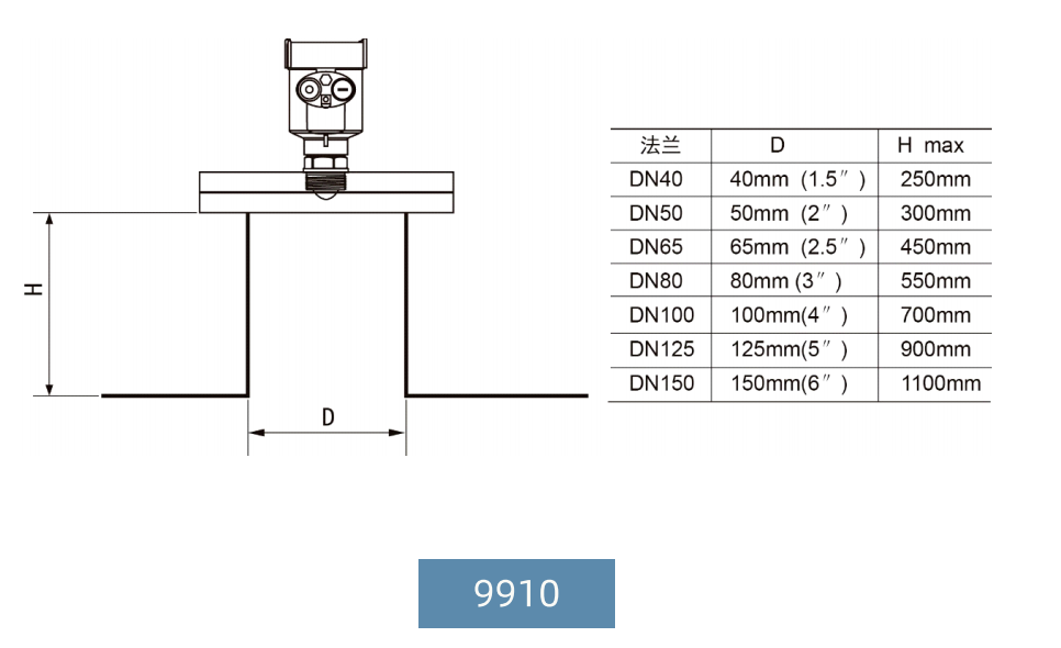
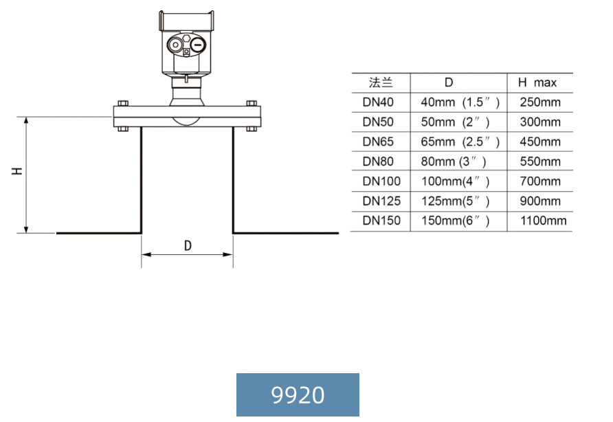
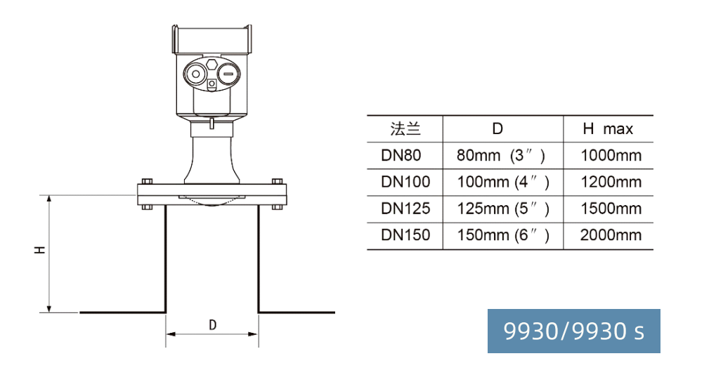
Installation connection diagram
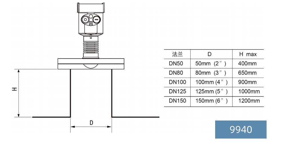
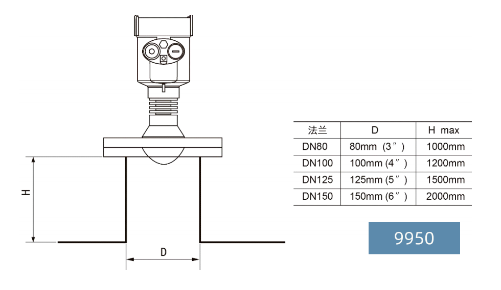
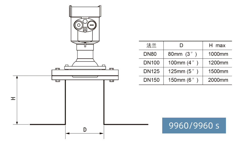
The maximum installation short pipe height H max depends on the installation short pipe diameter D and the size of the product launch angle.
Too long installation connection will affect the radar performance.
