Product Description
The high-frequency microwave pulse emitted by the guided wave radar propagates along the detection component (steel cable or steel rod), encounters the measured medium, causes reflection due to a sudden change in the dielectric constant, and part of the pulse energy is reflected back.The time interval between the transmitted pulse and the reflected pulse is proportional to the distance of the measured medium.
principle
The high-frequency microwave pulse emitted by the guided wave radar propagates along the detection component (steel cable or steel rod), encounters the measured medium, causes reflection due to a sudden change in the dielectric constant, and part of the pulse energy is reflected back.The time interval between the transmitted pulse and the reflected pulse is proportional to the distance of the measured medium.
Features of Guided Wave Radar Level Meter
Due to the advanced microprocessor and the unique Echo Disoverv echo processing technology, the guided wave radar level gauge can be applied to various complex working conditions.
A variety of process connection methods and types of detection components make the 70X series guided wave radar level gauges suitable for various complex working conditions and applications.Such as: high temperature, high pressure and small dielectric constant medium, etc.
Using pulse working mode, the transmission power of guided wave radar level gauge is extremely low, and it can be installed in various metal and non-metal containers without harming the human body and the environment.
illustrate
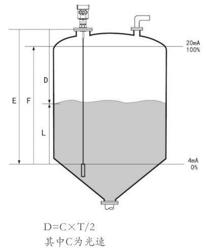
Guided wave radar is a measuring instrument based on the principle of time travel. The radar wave runs at the speed of light, and the running time can be converted into a level signal through electronic components.The probe emits a high-frequency pulse and propagates along the cable or rod probe. When the pulse meets the surface of the material, it is reflected back and received by the receiver in the instrument, and the distance signal is converted into a level signal.
The reflected pulse signal is transmitted to the electronic circuit part of the instrument along the cable or rod probe, and the microprocessor processes the signal to identify the echo generated by the microwave pulse on the surface of the material.The correct echo signal identification is completed by the pulse software, and the distance D from the surface of the material is proportional to the time travel T of the pulse:
Since the distance E of the empty tank is known, the level L is: L=ED
It is set by inputting the empty tank height E (= zero point), the full tank height F (= full scale) and some application parameters. The application parameters will automatically adapt the instrument to the measurement environment, corresponding to 4 - 20mA output.
Measuring range
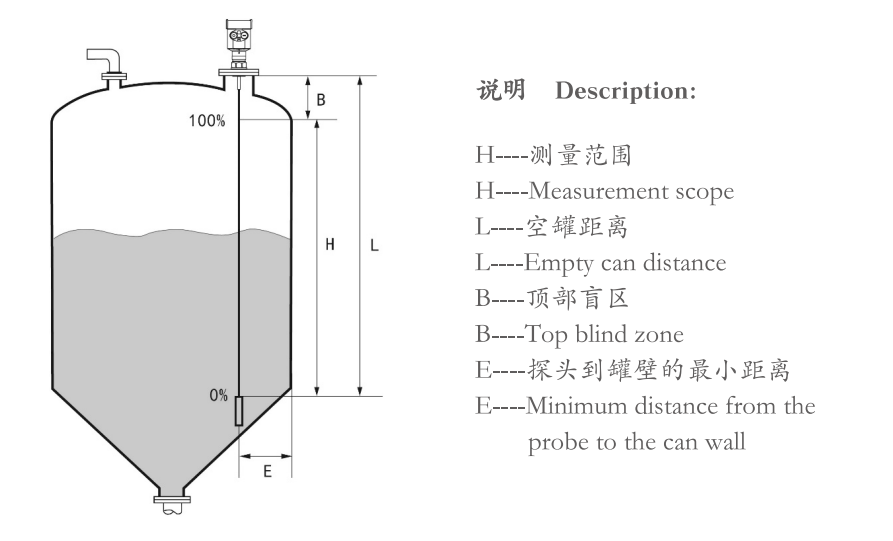
The top blind area refers to the minimum distance between the highest material level of the material and the measurement reference point.
The bottom dead zone is the distance near the bottom of the cable that cannot be accurately measured.
The effective measurement distance is between the top dead zone and the bottom dead zone.
Note Note:
Reliable measurement of the tank level can only be ensured when the material is between the top blind zone and the bottom blind zone.
installation requirements
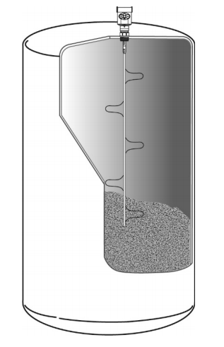
Make sure that the cables or rods do not come into contact with internal obstacles within the entire measuring range. Therefore, installations in the tank should be avoided as much as possible during installation, such as: personnel ladders, limit switches, heating equipment, brackets, etc.In addition, care must be taken that the cables or rods do not intersect the feed stream.
Installation Precautions
The highest material level must not enter the measurement blind area; the instrument must keep a certain distance from the tank wall, and the instrument should be installed as far as possible so that the direction of the cable or rod is perpendicular to the surface of the measured medium.Instruments installed in explosion-proof areas must comply with the national installation regulations for explosion-proof hazardous areas.The intrinsically safe enclosure is made of aluminum.Intrinsically safe instruments can be installed in places with explosion-proof requirements, and the instruments must be connected to the ground.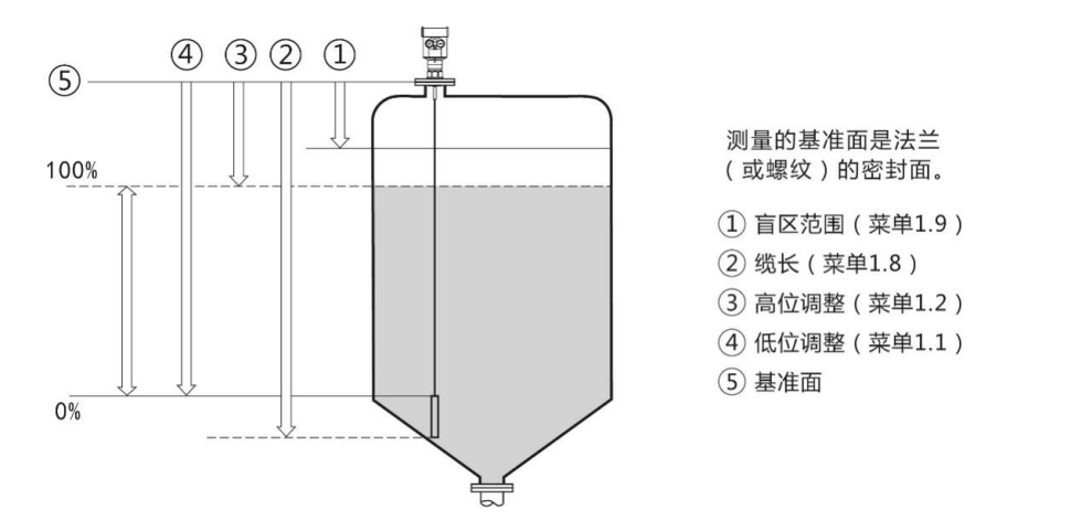
installation location
Keep as far away as possible from the outlet and inlet.The metal tank does not touch the tank wall and tank bottom within the entire measuring range.
It is recommended to be installed at 1/4 or 1/6 of the diameter of the silo, and the minimum distance from the tank wall is 1/10 of the measurement range.
The minimum distance between the cable or rod probe and the tank wall is 2300mm.
The bottom of the probe is 30mm from the bottom of the tank.
The minimum distance between the probe and the obstacles in the tank is 2200mm.
If the bottom of the container is tapered, it can be installed in the center of the tank top.
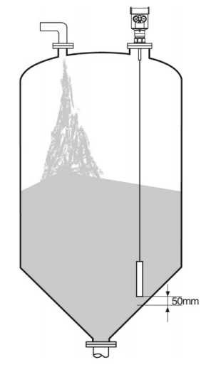
Measuring Features of Rod Radar Level Meter
Any medium with a dielectric constant of 21.8 can be measured.
Generally used to measure viscosity s500cst and not easy to produce adhesion medium.
The maximum range of the rod radar can reach 6 meters, and it is mainly used for liquid level measurement.
High penetrating ability to steam and foam, the measurement is not affected.
For the liquid measurement environment with large foam, the single-rod guided wave radar level meter should be selected for measurement.
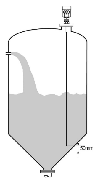
Measurement characteristics of double-cable radar level gauge
For liquids and light solid powders with relatively small dielectric constants, dual-cable guided wave radar level gauges can be used to ensure accurate measurement results.
Any medium with a dielectric constant of 21.6 can be measured.
Generally used to measure viscosity s500cst and not easy to produce adhesion medium.
The maximum range of the double-cable radar level gauge can reach 30 meters.
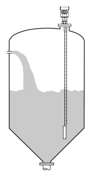
installation method
Reasonable installation can ensure long-term reliable and accurate measurement of the instrument
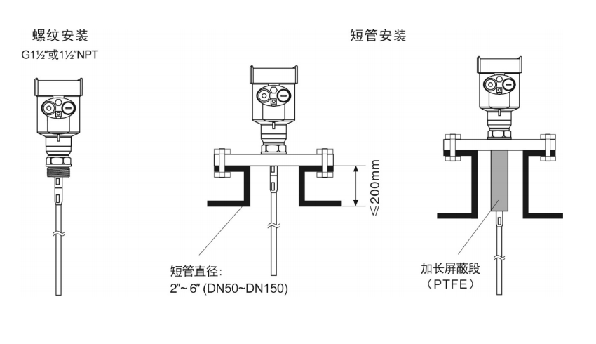
The guided wave radar level gauge adopts threaded and flanged connections, and can be installed on short pipes.The smaller the diameter of the installation nozzle, the shorter the length of the nozzle, and the more stable the measurement.When the diameter of the short pipe installed is 2' to 6', the height of the short pipe installed should be s200mm.If the short tube is long, it is better to shorten the short tube, or lengthen the shielding section of the sensor.
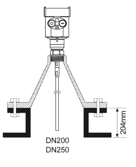
Installation in short pipes of DN200 or DN250
When the guided wave radar needs to be installed on a short pipe with a diameter greater than 200mm, echoes will be generated on the inner wall of the short pipe, which will cause measurement errors when the dielectric constant of the medium is low.Therefore, for a short pipe with a diameter of 200mm or 250mm, a special flange with 'horn interface' needs to be selected.
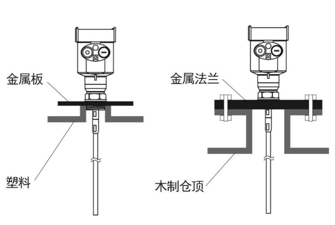
Installation on plastic tanks
Whether it is a cable or rod type, if the guided wave radar is to work properly, the process connection surface is generally metal.When the guided wave radar is installed on a plastic tank, if the tank top is also made of plastic or other non-conductive materials, the instrument needs to be equipped with a metal flange, and if it is threaded, it needs to be equipped with a metal plate.
Installation Notes
Rod probes can be up to 6 meters long, and cable probes can be used for storage tanks with a measuring distance of more than 6 meters.
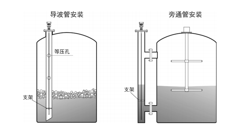
If there are many obstacles in the tank or it is too close to the probe sensor, a waveguide can be installed for measurement.
pull-down force on the cable
When feeding and discharging, the medium produces a pull-down force on the cable probe, and the pull-down force depends on the following factors:
A. Cable Length B. Alertness of materials C. The diameter of the storage bin D. The diameter of the cable
optimization of interference
Interference echo suppression: The programming and debugging software can realize the suppression of interference echo, so as to achieve the ideal measurement effect.
For media with a viscosity not greater than 500cst (only applicable to liquids), bypass pipes or waveguides can be used to avoid interference.
Installation of low dielectric constant liquids
For the medium with a dielectric constant greater than 1.3, a viscosity of s500cst, and not easy to cause adhesion, a waveguide can be installed for measurement, and the following effects can be achieved:
Excellent reliability, high precision
It can be used in any medium with a dielectric constant of 21.3, and the measurement has nothing to do with the conductivity of the medium
Obstacles in the tank and the size of the short pipe do not affect the measurement
Corrosive media measurement
If you measure corrosive media, you can choose a rod type or a cable type probe cover PTFE, PFA casing for measurement
Special instructions and precautions during installation
For guided wave radars with too long cables in field use, it is necessary to cut off the excess cables to ensure correct measurement, and the cables cannot be knotted, entangled or attached to other objects.
When cutting the cable, first cut off the power supply of the instrument, remove the cable, remove the screw on the weight, and cut from the bottom of the cable. After cutting, you need to reinstall the weight, and then turn on the power after the instrument is installed. and reset the parameters.
For the cable-type guided wave radar with casing, when the cable is too long, it is not allowed to intercept it by itself, and it needs to be returned to the original factory for interception.
For the instrument installed in the waveguide, it is necessary to use an insulating bracket to fix the radar probe to ensure that the radar probe (rod/cable) is concentric with the waveguide, otherwise the measurement will be affected due to vibration or false echo.
Correct installation
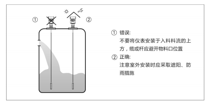
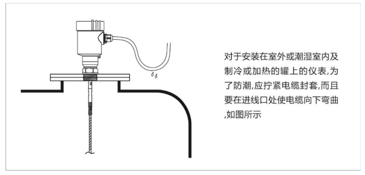
Moisture-proof
